
Mastering Automotive Relay Testing: A Complete Guide With a Multimeter
Introduction: Why Test Automotive Relays?
Relays are the silent workhorses of automotive electrical systems, acting as switches that allow low-power circuits to control high-power devices like headlights, fuel pumps, and fans. When a relay fails, it can cause frustrating electrical problems that are often difficult to diagnose. Knowing how to test automotive relays with a multimeter is an essential skill for any vehicle owner, DIY enthusiast, or professional mechanic. This guide delivers a detailed, practical approach to relay testing, including step-by-step instructions, real-world examples, and actionable troubleshooting advice.
Understanding Automotive Relays
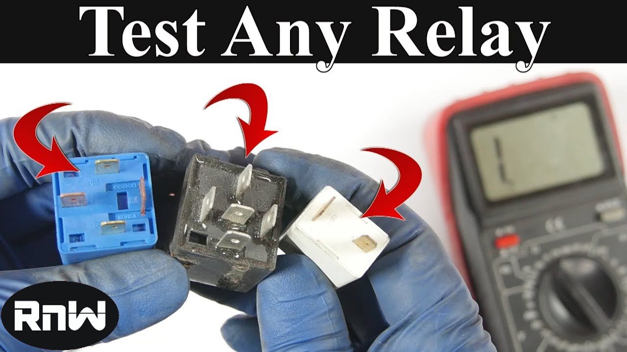
Automotive relays are typically electromagnetic switches with four or five terminals. They use a small control current to close (or open) a circuit that carries a much stronger load. The most common relay configuration is the four-pin (SPST) or five-pin (SPDT) type, with terminals labeled as 85, 86 (coil), and 30, 87, and optionally 87a (switching contacts). Each terminal has a specific function, often printed on the relay housing or detailed in your vehicle’s wiring diagram.
Key points to remember:
- 85 and 86: Connect to the relay coil, which creates a magnetic field when energized.
- 30: Common terminal for the switched circuit (power input).
- 87: Normally open (NO) output terminal (power output when relay is energized).
- 87a: Normally closed (NC) output terminal (only present in 5-pin relays).
Tools and Safety Precautions
Before you begin, assemble the following tools and observe these safety steps:
- Digital multimeter (capable of measuring resistance/ohms and voltage)
- 12V power source (for bench testing, such as a car battery or power supply)
- Jumper wires with alligator clips
- Protective gloves and eye wear
- Vehicle-specific wiring diagram (optional but recommended)
Always disconnect the relay from the vehicle’s electrical system before testing to prevent unintended short circuits or damage. If you’re unsure about the relay’s location, consult your owner’s manual or a reputable repair guide.
Step-by-Step Guide: How to Test an Automotive Relay With a Multimeter
1. Remove and Identify the Relay
Locate the suspect relay in your vehicle’s fuse or relay box. Remove it carefully, noting its orientation. Examine the pins and labels to identify coil and switch terminals. Some relays have diagrams printed on them; if not, reference your wiring diagram or search for your relay model online.
2. Test the Coil Resistance
Set your multimeter to the ohms (Ω) setting . Connect the probes to terminals 85 and 86 (the relay coil). A healthy relay coil typically shows resistance between 50 and 200 ohms , depending on the relay’s specifications [2] [3] [4] . If the reading is outside this range or shows “OL” (open loop), the coil is likely damaged and the relay should be replaced.
Example:
If your multimeter reads 100Ω, the coil is good. A reading of 0Ω (short) or OL (open) indicates a faulty coil.
3. Check for Audible Click (Bench Test)
To verify relay operation, apply 12V across terminals 85 and 86. You should hear a distinct “click” as the relay switches. This is the armature moving to close the contacts [2] . No click typically means a failed coil or mechanical issue.
Tip:
Use jumper wires from your 12V battery or power source, ensuring correct polarity and avoiding shorts.
4. Test the Switching Function (Continuity Test)
With the relay de-energized (no power applied to coil):

Source: kalale.rozblog.com
- Measure resistance between terminals 30 and 87 (NO). You should see infinite resistance (open circuit).
- If your relay has a pin 87a (NC), test between 30 and 87a. You should see 0 ohms (closed circuit).
With the relay energized (12V applied to coil):
- Measure between 30 and 87. You should now see close to 0 ohms (closed circuit), indicating the relay is switching correctly.
- Between 30 and 87a, the circuit should now be open (infinite resistance).
Example:
If you energize the relay and measure less than 1 ohm between 30 and 87, the switch is functioning. If you still see open circuit, the contacts are likely damaged or worn
[2]
[4]
.
Alternative Methods and Troubleshooting
Swapping With a Known-Good Relay
If you have an identical relay in your vehicle, you can temporarily swap them. If the problem moves with the relay, you’ve found the culprit. However, use caution-if an underlying circuit issue caused the failure, it may damage the replacement relay [3] .
Visual Inspection
Check for signs of corrosion, burning, or melting on the relay’s pins or housing. Physical damage often indicates overheating or a shorted circuit elsewhere in the vehicle.

Source: fity.club
Common Challenges and Solutions
- Intermittent operation: Test multiple times, as relays can sometimes work intermittently due to worn contacts.
- No click, good coil resistance: The mechanical parts may be jammed or corroded. Replacement is recommended.
- Relay tests good, problem persists: The issue may be with the wiring, fuse, or the load device itself. Continue diagnosing the circuit.
When to Replace a Relay
Replace the relay if:
- The coil resistance is out of specification.
- No audible click is heard when energized.
- The switching contacts do not open or close as expected.
- There are visible signs of damage, overheating, or corrosion.
Practical Applications: Real-World Examples
Suppose your car’s horn stops working. After checking the fuse and horn itself, you suspect the relay. Following the steps above confirms the relay coil reads OL (open loop) on your multimeter, indicating a failed relay. After replacement, the horn works again-demonstrating the value of accurate relay testing.
In another scenario, your cooling fan runs continuously. Testing reveals the relay contacts are stuck closed, even with no power to the coil. Replacing the relay restores normal fan operation.
Alternative Approaches and Additional Resources
If you lack a multimeter, consider having your relay tested at an auto parts store-many offer free electrical component testing. Alternatively, invest in a basic digital multimeter, readily available at hardware and automotive retailers, often for less than $30.
For those seeking more hands-on guidance, video tutorials such as the one from the NAPA Network or The Drive can provide visual demonstrations of each test step. Always ensure you’re referencing current, reputable sources for the most accurate techniques [2] [3] .
Key Takeaways
- Testing automotive relays with a multimeter is straightforward and requires minimal equipment.
- Always verify coil resistance and switching function separately for comprehensive diagnosis.
- Replace faulty relays promptly to avoid broader electrical problems.
- When in doubt, consult your vehicle’s manual or a professional technician.
Accessing Further Help and Information
If you need additional support, you can:
- Search for your specific vehicle’s wiring diagram using the make, model, and year.
- Visit reputable auto parts retailers for in-person advice or parts testing.
- Contact a certified automotive technician for complex electrical issues.
- Refer to your vehicle’s official repair manual for manufacturer-specific procedures.